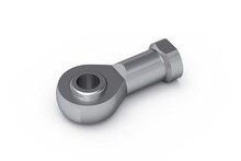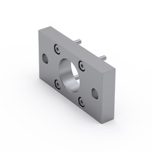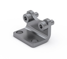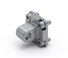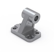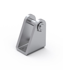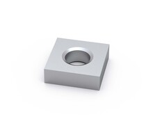
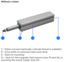
Rod eye SGS
Piston Rod Accessory SGS, galvanized steel
| Designation | Select all | CAD | Compare | Get quote | Lead Time * | Description | Ball Screw (d x l) | Max. Drive Torque Mₚ (Nm) | Max. Travel Speed Vmax (m/s) | Max. Rotational Speed nmax (min⁻¹) (rev/min) | No Load Torque M₀ (Nm) | Axial Dynamic Load Capacity Ca (N) | Max. Permissible Axial Load Fpa (N) | Max. Permissible Payload Horizontal mph (kg) | Max. Permissible Payload Vertical mpv (kg) | Max. Permissible Radial Load on Shaft Fpr (N) | Moved Mass (kg) | Mass of the Mini Electric Cylinder mMCE (kg) | Mass Moment of Inertia JMCE (10⁻² kg cm²) | Planar Moment of Inertia ly (cm⁴) | Planar Moment of Inertia lz (cm⁴) | |
|---|---|---|---|---|---|---|---|---|---|---|---|---|---|---|---|---|---|---|---|---|---|---|
|
|
|
2 | Without motor | 6 × 2 mm | 0.06 | 0.150 | 4500 | 0.02 | 1900 | 170 | 57 | 14 | 25 | 0.06 + 0.0004 × Abs. stroke + 0.0004 × E | 0.15 + 0.0013 × Abs. stroke + 0.0004 × E | 0.28 + 0.0007 × Abs. stroke + 0.00004 × E + 0.1013 × mload | 2.10 (cylinder profile) | 1.98 (cylinder profile) | ||||
|
|
|
2 | Without motor | 6 × 6 mm | 0.10 | 0.450 | 4500 | 0.02 | 1700 | 90 | 30 | 7 | 25 | 0.06 + 0.0004 × Abs. stroke + 0.0004 × E | 0.15 + 0.0013 × Abs. stroke + 0.0004 × E | 0.33 + 0.0011 × Abs. stroke + 0.00036 × E + 0.9119 × mload | 2.10 (cylinder profile) | 1.98 (cylinder profile) | ||||
|
|
|
2 | Without motor | 8 × 2 mm | 0.13 | 0.150 | 4500 | 0.04 | 2000 | 375 | 126 | 31 | 50 | 0.12 + 0.0005 × Abs. stroke + 0.0005 × E | 0.31 + 0.0023 × Abs. stroke + 0.0005 × E | 0.70 + 0.0025 × Abs. stroke + 0.00005 × E + 0.1013 × mload | 6.42 (cylinder profile) | 6.58 (cylinder profile) | ||||
|
|
|
2 | Without motor | 8 × 8 mm | 0.53 | 0.600 | 4500 | 0.05 | 1500 | 375 | 126 | 31 | 50 | 0.12 + 0.0005 × Abs. stroke + 0.0005 × E | 0.31 + 0.0023 × Abs. stroke + 0.0005 × E | 0.88 + 0.0033 × Abs. stroke + 0.00077 × E + 1.6211 × mload | 6.42 (cylinder profile) | 6.58 (cylinder profile) | ||||
|
|
|
2 | Without motor | 10 × 3 mm | 0.37 | 0.225 | 4500 | 0.07 | 3500 | 695 | 233 | 58 | 100 | 0.20 + 0.0010 × Abs. stroke + 0.0010 × E | 0.67 + 0.0043 × Abs. stroke + 0.0010 × E | 2.77 + 0.0057 × Abs. stroke + 0.00022 × E + 0.2280 × mload | 25.37 (cylinder profile) | 25.6 (cylinder profile) | ||||
|
|
|
2 | Without motor | 10 × 10 mm | 1.23 | 0.750 | 4500 | 0.09 | 3200 | 695 | 233 | 58 | 100 | 0.20 + 0.0010 × Abs. stroke + 0.0010 × E | 0.67 + 0.0043 × Abs. stroke + 0.0010 × E | 3.23 + 0.0081 × Abs. stroke + 0.00249 × E + 2.5330 × mload | 25.37 (cylinder profile) | 25.6 (cylinder profile) |
*Green: Normally in stock, contact us for current status. Blue: Contact us for delivery time.
| Designation | Select all | CAD | Compare | Get quote | L1 | L2 | L3 | L4 | L5 | L6 | L7 | L8 | L9 | L10 | L11 | L12 | L13 | L14 | L15 | L16 | L17 | L18 | L19 | L20 | L21 | L22 | L23 | L24 | L25 | L26 | L27 | L28 | L29 | ZK1 | ZK2 | U1 | U2 | U3 | U4 | U5 | |
|---|---|---|---|---|---|---|---|---|---|---|---|---|---|---|---|---|---|---|---|---|---|---|---|---|---|---|---|---|---|---|---|---|---|---|---|---|---|---|---|---|---|
|
|
|
50 | 26 | 16 | 10 | Ø 12 | 3.5 | Ø M6 × 1 | 3.2 | 8 | Ø M2.5 | 25 | 21 | 13.5 | 19.25 | 4.4 | Ø M4 | 8 | 19 | 17 | 18 | Ø M2.5 | 8 | 14 | 7 | Ø 5 (h7) | Ø 17.6 | Ø 20 (h7) | 4.5 | 2.3 | 10 | 10 | 2.2 | 4.2 | 2.8 | 1.4 | 1 | ||||
|
|
|
50 | 26 | 16 | 10 | Ø 12 | 3.5 | Ø M6 × 1 | 3.2 | 8 | Ø M2.5 | 25 | 21 | 13.5 | 19.25 | 4.4 | Ø M4 | 8 | 19 | 17 | 18 | Ø M2.5 | 8 | 14 | 7 | Ø 5 (h7) | Ø 17.6 | Ø 20 (h7) | 4.5 | 2.3 | 10 | 10 | 2.2 | 4.2 | 2.8 | 1.4 | 1 | ||||
|
|
|
65 | 32 | 20 | 12 | Ø 14 | 5.5 | Ø M8 × 1.25 | 4 | 8 | Ø M4 | 32 | 22 | 13.5 | 22.8 | 4.4 | Ø M5 | 8 | 24.5 | 24.5 | 24.5 | Ø M3 | 8 | 14 | 7 | Ø 5 (h7) | Ø 22.6 | Ø 25 (h7) | 4.5 | 2.3 | 12 | 13 | 3.2 | 5.8 | 3.6 | 2 | 1 | ||||
|
|
|
65 | 32 | 20 | 12 | Ø 14 | 5.5 | Ø M8 × 1.25 | 4 | 8 | Ø M4 | 32 | 22 | 13.5 | 22.8 | 4.4 | Ø M5 | 8 | 24.5 | 24.5 | 24.5 | Ø M3 | 8 | 14 | 7 | Ø 5 (h7) | Ø 22.6 | Ø 25 (h7) | 4.5 | 2.3 | 12 | 13 | 3.2 | 5.8 | 3.6 | 2 | 1 | ||||
|
|
|
80 | 38 | 22 | 16 | Ø 18 | 7 | Ø M10 × 1.25 | 5 | 12 | Ø M6 | 45 | 32 | 20 | 30.5 | 4.4 | Ø M6 | 12 | 34 | 34 | 34 | Ø M4 | 10 | 16 | 8 | Ø 8 (h7) | Ø 31.6 | Ø 34 (h7) | 4.5 | 2.3 | 16 | 17 | 4.2 | 7.5 | 4.7 | 2.5 | 1.2 | ||||
|
|
|
80 | 38 | 22 | 16 | Ø 18 | 7 | Ø M10 × 1.25 | 5 | 12 | Ø M6 | 45 | 32 | 20 | 30.5 | 4.4 | Ø M6 | 12 | 34 | 34 | 34 | Ø M4 | 10 | 16 | 8 | Ø 8 (h7) | Ø 31.6 | Ø 34 (h7) | 4.5 | 2.3 | 16 | 17 | 4.2 | 7.5 | 4.7 | 2.5 | 1.2 |